|
Drzewiecki Design Home
Cockpit
HISTORY OF BUILD
GALLERY/VIDEO
INFORMATION
|
|
Drzewiecki Design Home Cockpit System
Construction start: October 2005
Construction finish:
January 2009
The beginning
Putting in a seat
Rudder pedals
3rd monitor
Main panel
Glass cockpit
Overhead
End of
construction (part 1)
Demolishing
Radio Stack
New PC, network
config
Main Panel
Visual System
GoFlight modules
Glareshield and windshield
End of
construction
Please
note that many links below are broken.
|
|
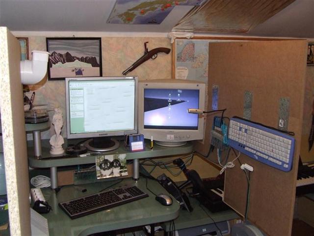
I began the construction
by ordering two 16mm chipboards. The walls
were to be 160cm high,
what gave a big surface to arrange. On
the right wall I mounted one of the keyboards (RIGHT_KEY) and one of
the six USB HUB's. I needed to design and build an appropriate
ventilation system
because not only the cabin's small size but also the heat of the
computer were causing problems with air circulations an making
breathing inside the cabin very difficult. On the left wall a
ventilator for 220V is visible that supplies the air inside the
cabin. |
 |
|
The next stage
entailed construction of the main panel.
I
was wondering how it should be done so
that it could be easily removed together with the yoke whenever I
needed to use the computer for writing or other things.
There were
few ideas. The
first one and the simplest was to place hinges on the left side of
the panel, which would allow the entire
unit to be raised and fixed to the wall when the joke was unbolted
from the desk.
However this solution was not successful because of
the tremendous technical difficulties which it would create (such as
endurance). |
.JPG) |
|
I came up with a
different idea. The whole main panel was to be installed on guides
and moved up together with the joke.
With adequate
strengthening and a great accuracy in work, this idea seemed to be
possible. However it was abandoned because of the great weight of
the panel, which
besides the joke was to include another monitor (displaying various
gauges) and 4
GoFlight modules including the MCP Pro. The whole set was
difficult to lift and the idea of placing a motor on the cockpit
roof was rather unrealistic. |
.JPG) |
|
At this stage I realized that it was necessary to
postpone the construction of the main panel, and to take care of
remaining elements.
Undoubtedly, one
of the most important elements was the throttle. It was built, using
typical home methods. I removed a potentiometer from my old joystick
(which miraculously was still in my garage) and I build the device
on its basis. I used a stick from a rolling-pin, which after some
bending fitted perfectly. I set the chip so that when throttle stick
was back the reverse thrust during landing was automatically on.
I
placed a bulb in a way that it illuminated the stick from the
inside. Four light
switches were installed on the front wall.
|
.JPG) |
|
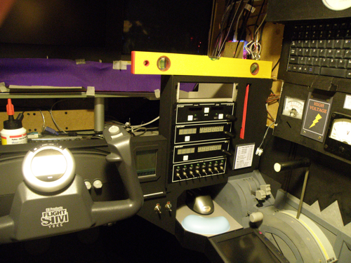
In order to
monitor what
is going on
in various parts of the cockpit I've built a diagnostic panel,
consisting of three voltage meters (one made in 1946!). One of them
measures the current outlet voltage (230V), another the
illumination
circuit (7V), and the third one the voltage on the computer circuit
behind the power unit (7V). The panel is equipped with a clock and a
data computer containing basic information about various airports -
like frequencies, runways length, altitude etc.. It is highlighted
and has a touch screen (like in palmtop), which is helpful during
night flights.
|
.JPG) |
|
After finishing,
all element were painted and installed on the right wall of the
cockpit. On the throttle wall there is a board painted in a
different color, which in case of breakdown is easily removable.
This allows fast access to the internal parts. Similar access point
is installed on the diagnostic panel - it reads "High Voltage". The
board was cut in such a way so that one could have access to all the
cables and wires under the desk. |
.jpg) |
|
The carpet under the
cockpit was
shamelessly
cut out and replaced with gray plastic foil. I
bought an old Volkswagen seat through an internet auction, which
after renovation was tested (turned out
extremely
comfortable) and then placed
on a gray-painted platform. The platform was needed for two reasons:
first, the seat was extremely low. Second, it had metal guides,
which were to be attached to a flat surface. The whole unit was
assembled in a garage and then not so easily transported and
installed in the cockpit. |
.JPG) |
|
.jpg) .jpg) |
|
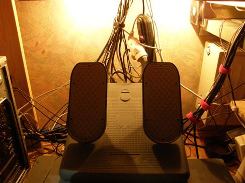
The
construction of the platform resulted in the next consequences.
There were no options to normally place the pedals.
There was a need for a strong
frame containing two columns that was to be placed in the cobweb of
wires and cables.
I placed the
pedals under a certain angle,
so the structure was even more realistic and comfortable to use. Of
course, they were also painted gray.
.JPG) |
|
In the mid of 2006
I bought
NaturalPoint TrackIR 4 PRO. This device has completely changed
the visual flights. I described how it works and my opinion about
the product in one of the topic of the
Drzewiecki Design forum.
For a proper
functioning of TrackIR small metal reflecting plates were necessary.
I installed them on a headphone set, using a 2mm cardboard. Up and
down head movement would often produce errors due to the
interference of hair. The problem was solved when with application
of the coupler visible in the picture.
|
.JPG) |
|
In the meantime I drastically modernized my computer
equipment, preparing myself to the arrival of a new simulator - FSX.
I bought a new Intel Pentium D 930 3GHZ (x2) processor and two
synchronized graphic cards, GF XFX6800, 256MB each.
After a short break related
to the lack of time I resumed my work on the project, thinking that
it was about time to build the main panel.
During my trip to China I made a purchase of 15"
monitor, which I built into the right part of the panel.
It was also
necessary to build an additional small shelf for the mouse
since the main shelf was already used for the screen. The monitor
was set in a frame (slightly wider than its thickness) and fixed
permanently with some supports to the right wall and the desk. Two
main monitors were connected to a single graphic card and the third
monitor to a separate one. |
.JPG) |
.JPG) .JPG) |
|
Now I had to think how to
transform the cockpit into a comfortable office desk. I came up with
an idea that only the mid section of the panel could be movable,
while the yoke could be withdrawn inside with a regular keyboard
replacing it. The mid section was put equipped with guides and
painted. Next, I built a hood connecting the two walls. On the right
side I made a hole for a planned
GoFlight panel and
NumPad, enabling communication with
ATC. The mid section was lit, providing light for the keyboard
when the yoke was hidden.
.JPG) .JPG) .JPG) .JPG) |
|
Later, I bought a
used joystick and removed all the potentiometers out of it, which I
used for building a new module for controlling spoilers (airbrakes),
fuel mixture, and the propeller. The module has two buttons, one of
which controls the TO/GA engine thrust, and another the parking
brakes. The buttons were made of keys removed from a slightly
damaged keyboard and were connected to an integrated circuit. A
little bulb was inserted inside the module. The handles were taken
from a CH yoke. The module was placed in front of a monitor by the
throttle on the mouse shelf.
.JPG) .JPG) .JPG) .JPG) |
|
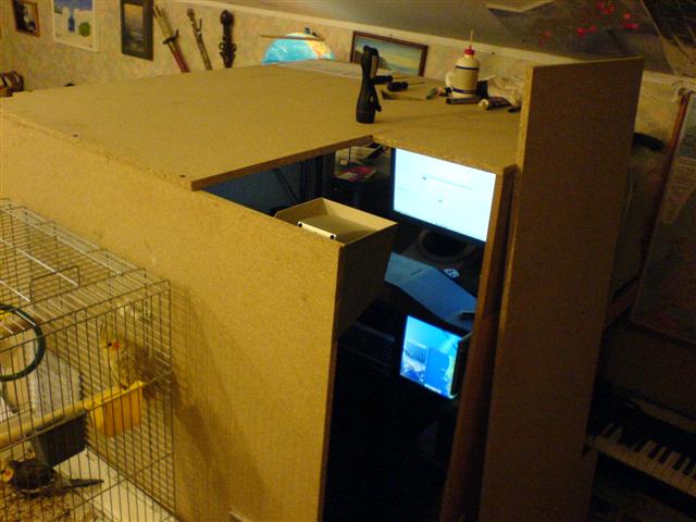
The next stage
involved building a roof. In the roof I made three openings: a
larger extension of the door opening (for easier entrance and exit),
for cables and wires, and for a network card antenna. The 16mm
chipboard was attached with seven screws to the walls. This produced
some unique acoustic environment -the wood started to resonate and
the whole cockpit would vibrate at low sound. Despite the winter,
the temperature inside the cockpit significantly increased.
In the cabin, an unusual acoustics was felt - the wood begun to
resonate and whole cabin vibrated at low tones. |
 |
|
After
several-week break and a failed attempt to switch to a new
MSFS FSX
as well as after formatting hard disk, I faced a number of days,
during which I would have to install various programs and then
configure them. Due to huge hardware requirements of the FSX, I
concluded that buying new equipment as compared to what could be
achieved by some additional software on the old simulator wasn't an
investment worth of making. I decided to buy a few accessories,
which drastically improved the quality of the graphics on my FS2004
- Active Sky
6,
Ground
Environment Pro,
FS Global 2008,
Ultimate Terrain USA and
Ultimate Terrain Europe including
Eastern Europe. Flying has become extremely realistic visually
since then.
|
|
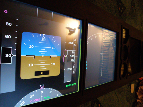
In the beginning of March 2007 I decided to finally program and
finish the displays in the
glass cockpit. Just now I could make use of the third monitor,
which displayed PFD (FreeFD),
Navigation Display with
TCAS (vasFMC),
weather radar (Active Sky), as well as additional speedometer and
altimeter (FreeFD). The frames of the displays were made from
cardboard and then painted black. The software was configured so
that when computer was turned on, the whole set of displays was
loaded automatically.
|
.JPG) |
.JPG) .JPG) |
|
The next stage of
the
realization of the
project was the
enclosing of
front monitors, which meant that they had to
be wrapped in black cardboard, closing the gap between the monitors
and the panel. Many element needed to be heavily framed
because of
their equalizing or supporting function..
A new ventilation duct for the pilot was added. All cables and wires
were bundled in preparation for a new
overhead panel. In addition, the entire cockpit was vacuumed and
sterilized. |
.JPG) |
.JPG) .JPG) |
|
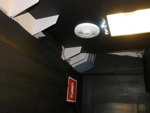
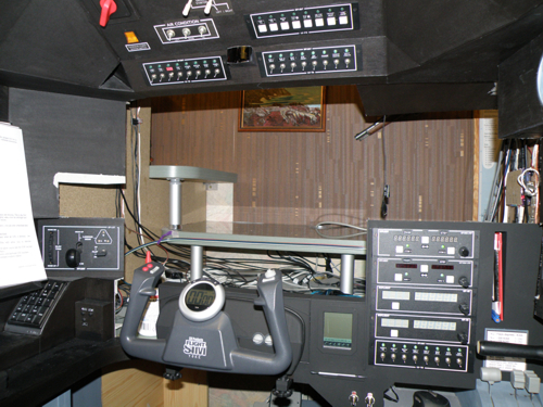
At the end of April 2007 there
came the time (which I so much kept putting off) for building an
overhead panel. I began with making a special platform to be located
at the same level as the top borderline of the main monitor that
would be a framework for other elements of the panel as well as the
base for a vent of one of the ventilation ducts. I concluded that it
would be technically impossible to make it in one piece, so I
decided to divide the panel into four parts (plus one in the end).
The first part (with two GoFlight panels) is shown on the photos.
|
.JPG) |
.JPG) .JPG) |
|
The third and fourth segments were comparatively easy
to make. The third one contained an illuminated keyboard, and the
fourth one a 230V light bulb
with a switch. The housing of the light was covered with aluminum
foil for better luminosity (a few year ago I found out that aluminum
foil is a good conductor of electricity - now I'm rather careful).
.JPG) .JPG) |
|
The second segment
was the most difficult to make -
currently equipped with a main power switch for the whole cockpit, a
switch for all systems of the overhead panel (I couldn't use
ventilation for some time due to its lack), 3 ventilation switches,
5 cockpit light switches, 2 starters, and a GoFlight panel. Under
the roof an additional keyboard needed to be installed for
controlling the starters. When the segment was ready, it was first
tested and then
turned around stuck to the ceiling of the cabin.
|
.JPG) |
.JPG) .JPG) |
|
The remaining
elements were also connected and after a several-week-long
assembling
of all the needed elements the panel
could be treated as finished. Three
ventilation systems were finally working (5 fans, which
tremendously
normalized the temperature inside the cabin.
I could finally remove the awful halogen lamp, which was used for
illuminating the inside - it was replaced with the top light from
the overhead panel as well as a special 12V electric installation,
illuminating all strategic elements of the cockpit. |
.JPG) |
|
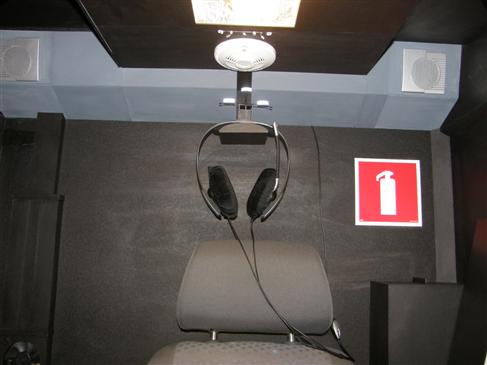
Due to the tight
enclosure of the monitors, I moved TrackIR 4 PRO to the first
segment of the overhead (between the GoFlight panels), which
significantly improved the accuracy of the device. The next stage
included various tests and an initial tuning of the systems. I may
add that all the switches were easily available, e.g. at Internet
auctions, so was the lit keyboard (half price). The overhead was the
last of the most complex elements of the cockpit. |
.JPG) |
.JPG) .JPG) |
|
In the mid of
2007, after a little longer break than originally expected, we
finally managed to fully configure the cockpit equipment. The MCP
panel had never worked properly since the time we ordered it from
GoFlight. Two successive panels were sent back to the manufacturer.
Only the third one, which I received 6 months after the original
order, met all the requirements. Its proper installation however
caused some changes to be implemented in half of the remaining
equipment, which in consequence resulted in a partial disassembling
of the right wall of the cockpit. After successful installation of
all the elements, the cockpit became fully functional for the first
time.
.JPG) .JPG)
Since I started more online flights
over the Vatsim network and these flights require a constant
presence of maps, I designed a special shelf for maps, which I
attached to the left wall of the cockpit. There is an open space
over the shelf and the shelf itself can be used as an arm support,
which improves comfort for the pilot manually handling the control
wheel. The framework was made of 2-3mm cardboard.
.JPG) .JPG) |
|
A few months
lapsed and in the mid December 2007 I could finally say that the
front part of the cockpit, which starts form the entrance door, was
completed. I have modified and painted the ceiling by the Overhead
panel. The floor has been changed and the right wall by the throttle
is finished and sealed. In addition, I have fixed the seat platform
down to the floor, because it used to have a tendency to move around
all over the place. It is also the time for testing the new versions
of alpha VasFMC 2.0 and preparation for the World Flight 2008. |
.JPG) |
.JPG) .JPG) .JPG) .JPG) |
|
The next stage
involved painting the whole interior of the cockpit as well as
covering the frame so that no elements, such as supports and wiring,
are no longer visible. I also took care about the wires near the
pedals.
    |
|
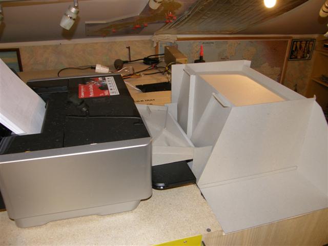
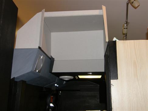
The last element
of the design was a fragment of the roof near the cockpit door. The
part was connected to a printer so that all printouts could go
directly into the cockpit. This allows all printed materials to be
received in the cockpit without opening the main door. The paper is
delivered through a small slot in the Overhead panel. The roof was
carefully fitted to the door and sealed. During the daytime the
interior of the cockpit is pitch black
after the door is closed.
|
 |
|
  |
|
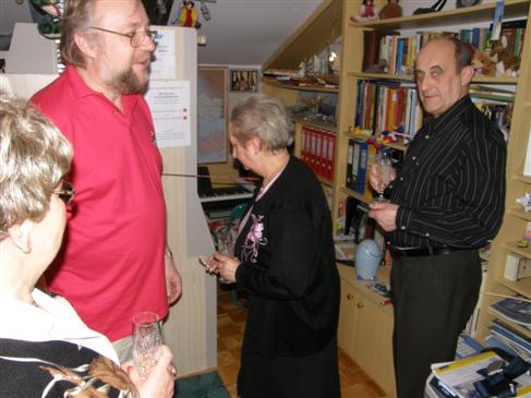
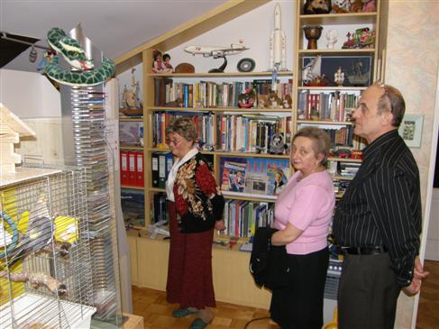
After over two years the cockpit was finally completed.
On 31 December, 2007 a modest Grand Opening was held during
which all the basic elements of the cockpit were
demonstrated. Some of the invited pilots could test their
skills. I would like to thank Andrzej Olejniczak and Edyta &
Jacek Miazek without whom the completion of this project
would have been impossible. |
 |
|
      |
|
After a long time flying on the finished
Version 1 of the cockpit I decided to start upgrading the whole
setup. The construction process started on October 2008 and lasted
four months. I upgraded a lot of things in my cockpit including
visual system, main panel, network configuration and much more. See
the details below.
|
|
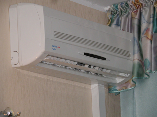
After a really hot summer and really big
problems with overheating the cabin I decided to invest into an
effective air condition system. This was a great decision. I bought
it in the Internet and it was quite cheap however its working
parameters were good enough. Anyway, it changed the climate in my
room completely. Usually there was two degrees more in the cockpit
than in the rest of my room. Right now I have a stable temperature
all the time: 21C and a temperature in the cockpit does not exceed
23C. This is good not only for a pilot but also for a computer.
Later I will upgrade also the interior ventilation system as it got
quite dirty and fans are turning slower than they should. All in all
I would recommend an air condition system for every cockpit builder! |
 |
|
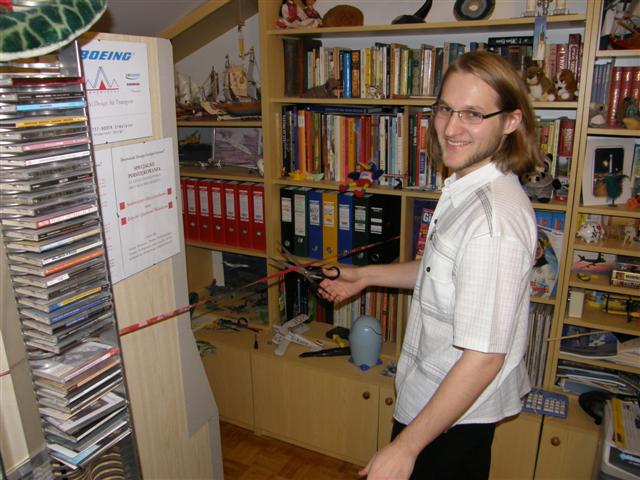
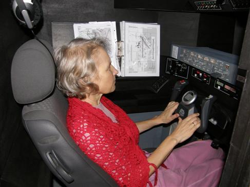
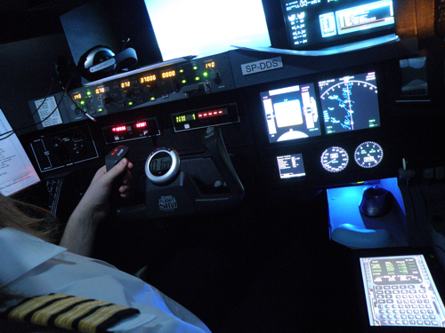
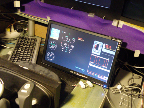
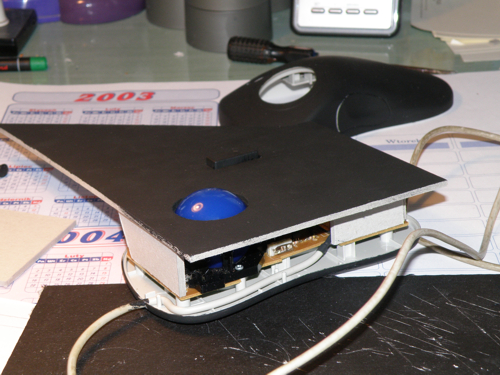
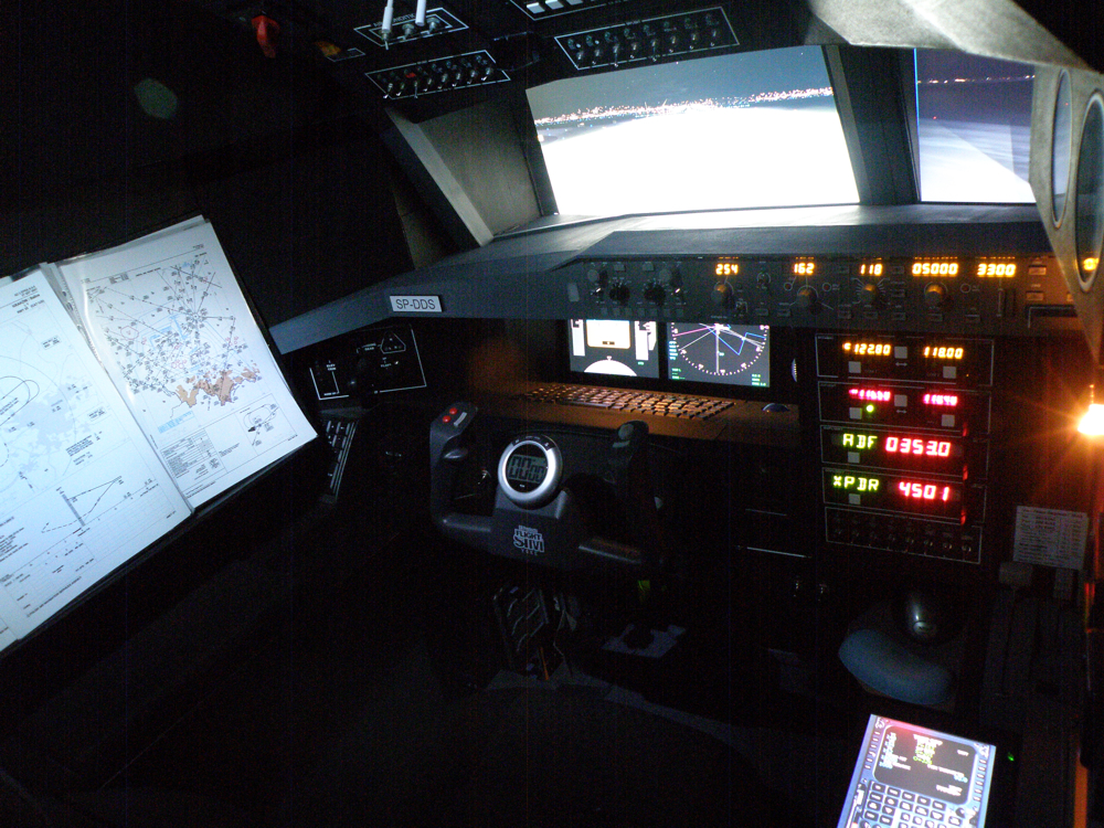
For the whole last year I was thinking about a
real FMC in my cabin. Of course getting it was not a problem however
configuring everything to work with the rest of the cockpit was
something I haven't been dreaming about. A hardware FMC is also very
expensive and requires a special software (like Project Magenta). I
am still using VasFMC as my glass cockpit displays and flight
management computer (I am not planning to change that) so this
seemed to be quite difficult. After couple of months someone told me
a great idea. Using a touch screen designed as a car entertainment
system would do the job. Yes, it really did! The screen works as a
standard monitor, it is just small and that's why I can still get out
of the cabin. I located it next to the throttle as it is usually
there in the real world. Finger press work the same as a mouse click
so instead of clicking buttons on a screen I can do the same by
pressing them with my fingers on the touch screen. Besides that I
finally got a pilot's shirt (captain version) so now I can be
dressed properly when flying as you can see below!
  |
|
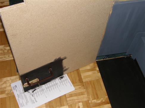
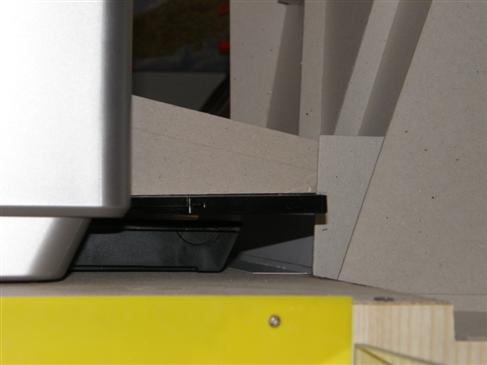
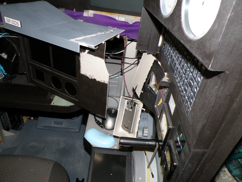
Although it was not easy to do, I have finally
deconstructed the main panel of the cockpit. It was fixed better
than I thought so I had to cut and actually destroy more than was
expected. Anyway, the center module and the one with a display were
mounted together outside the cockpit and obviously they required
some extra work to look normally. This is how tonight's hardcore
looked like:
  |
|
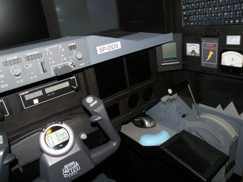
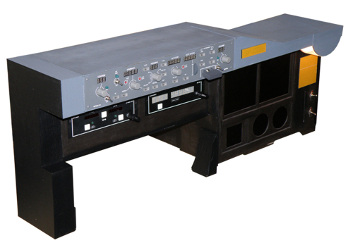
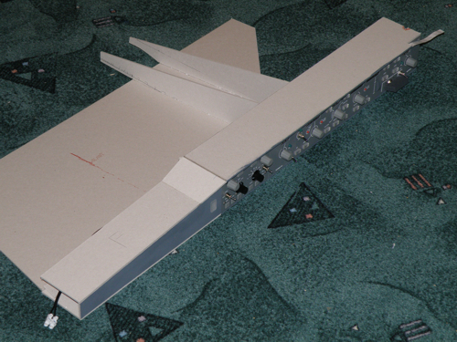
When the total demolish was completed I
decided to put the whole main panel together and sell it as a
standalone hardware. I have added some extra things like a light
(right upper corner) and some switches. Finally everything was
painted black and grey. The panel included a monitor as well as all
required software.
|
 |
|
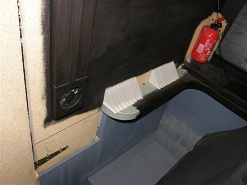
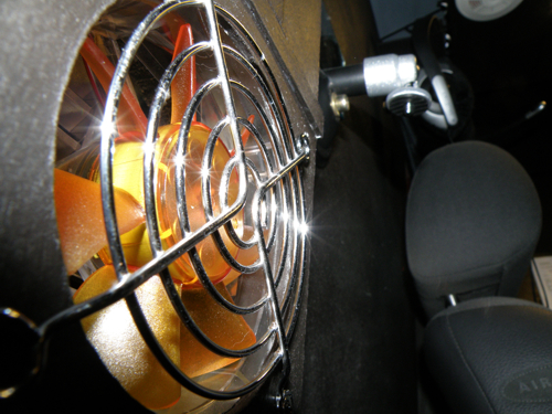
After couple days I have fixed the ventilation
system - two new fans did the job. As I was writing in the Version 1
description, a ventilation system is a very important thing for
every cockpit builder. You really need to think about it during a
construction. Remember that PCs as well as LCD monitors produce a
lot of heat that can kill a processor, graphic card or other PC
components during long flights. Even some problems with breathing
may occur. Of course I am talking about a closed cabin where there
is no fresh air from outside. The fan on the picture is actually
used to bring out a warm air from the cockpit. There is one more fan
for the same task and four bringing in a cold fresh air. Good air
circulation makes even the longest flights comfortable. |
 |
|
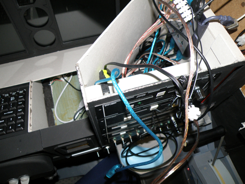
Few days lapsed and my radio stack panel has been
completed. I made it traditionally with a 3mm cardboard and painted
it black. Two GF-46, GF-T8 and GF-166 were mounted (still waiting
for another GF-166). The panel has been fixed in its position and
wired to a new 7-port USB hub (I bought three of them to upgrade
these connections as well). The radio stack panel includes two
switches that will be used to turn on a MCP light and a backlight.
There is also a place for my notepad. I use it often to copy
clearances and position reports during oceanic flights. Before there
was no place to put it in.
  |
|
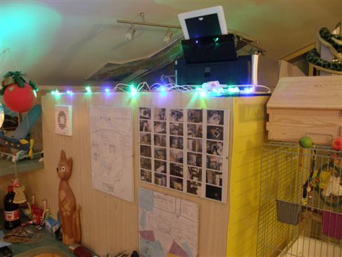
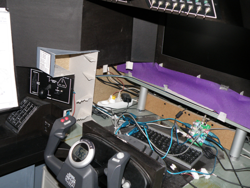
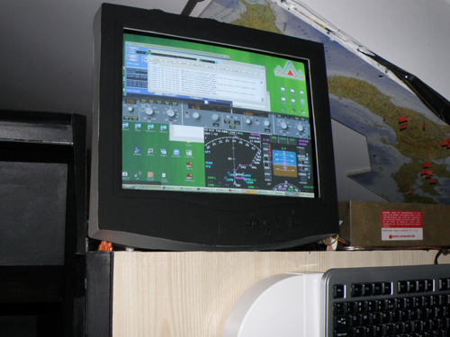
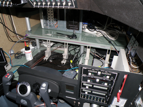
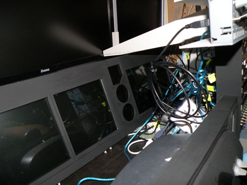
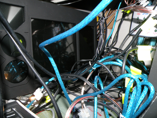
This picture was made when I finally cleaned
the whole cabin and checked all wire connections. I realized that
there were many unused cables that were left since the very
beginning of construction process. My project changed couple times
and I guess sometimes there was no point of taking those cables out
of the cabin. Anyway, I used some of them now and the rest was
trashed or just put somewhere outside the cabin. As you can see, I
said goodbye to my old monitors as well. One of them was put on a
roof of the cockpit to control the second PC (actually the PC on
which Flight Simulator has been running before), the second one was
connected to my laptop and now I use it for some graphics designing. |
 |
|
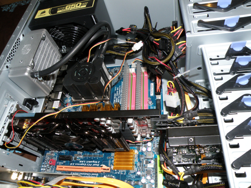
As I mentioned above, I decided to downgrade my Flight
Simulator PC to a Client PC role. Although it worked really good
with a plain FS2004 it's technical specs were not enough for online
flying with the whole cockpit connected. I have put my old PC behind
new monitors and bought a new PC that was placed inside the cabin.
Here is its basic specification:
Processor: Intel Core 2 Duo E8600, 3.33GHz, 1333FSB, 6MB Cache
Graphic card: ASUS EAH4870 DK Radeon HD4870 1GB DDR5 (256bit)
Motherboard: Gigabyte GA-EP45T-DS3R
RAM: Corsair XMS3 DHX 2x2GB 1600MHZ DDR3
Power unit: 650W
I have tested this setup in the most heavy
conditions and it seemed to keep a 25 FPS limit all the time, with
all my add-ons installed plus full Ultimate Traffic in Chicago KORD.
Of course a problem with cooling occur but it only concerned the
graphic card. It is not solved yet (standard 59C, max 68C) but I
guess I will just make a hole in a wall where this PC is standing
and put another fan there. As soon as I do this I may think about
some overclocking work. Why not? |
 |
|
I probably spent the most time configuring the
network. I have never done this before as my setup was always
running on one PC. Now I know that advantages of putting all
stand-alone applications on Client PC are really huge and very
comfortable in the same time. My whole cockpit setup starts on "one
click" (actually two clicks, I need to start two computers). Power
switch for the Client PC is placed on the main panel so I don't need
to go out of the cabin. After Windows is loaded,
batch files on both computers are automatically started from
Autostart folder. These files open all required applications in a
specific order with programmed delays if needed. From FS computer
only FS, Fuel Planner, ScreenShooter and obviously FSUIPC are
launched. Client PC starts WideFS, VasFMC, FreeFD, Active Sky,
GFKey, GFdisplay, pmSounds and FSInn. All applications start working
automatically, I don't need to do anything more except for opening
ATC, chat and WX windows in FSInn and clicking on VATSIM to connect
to the network. Even Flight Simulator loads a default flight itself
(I need to load a default flight first to have front views properly
aligned). Afterward I just need to fill in a flightplan and I am
ready to fly. This makes actually three steps to complete to be
prepared for an online flight and just one step for an offline
flight - both PCs starters on. Easy, yep? |
 |
|
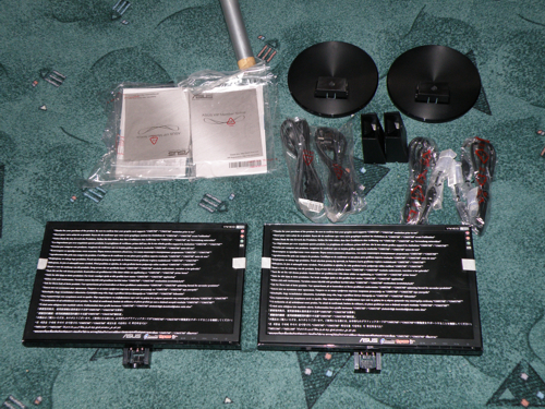
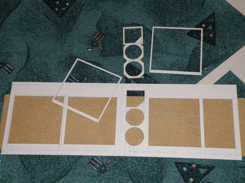
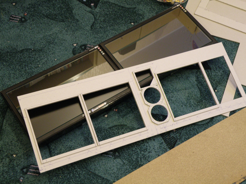
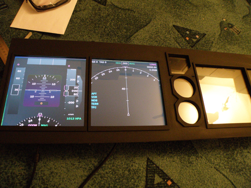
Here is a short story about the
main panel I constructed. Its very simple, made from 3mm cardboard.
I think the photos below are clear enough - there are 2 layers, base
and top for frames. Two 16" panoramic LCDs are used. I have put a
glass in front of the monitors like it is in the real world. At
least I think so - "glass cockpit displays" should have some glass
elements, right?. I like the final effect a lot - displays seem to
show more contrast and sharper shapes. Its just a test on the
pictures below so don't worry about this green background. As the
main displays VasFMC is used and FreeFD as the standby panel. This
is actually very useful too - if one software crash there are still
another instruments to read. I have put all important information
from FSInn on the very right screen - it is not visible when you sit
normally on a seat but clearly visible if you get closer to the main
panel. This is how I wanted it to be.
 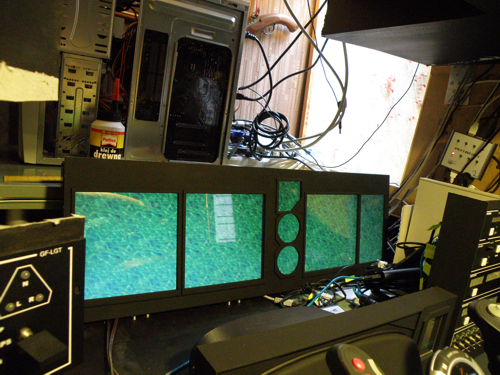 |
|
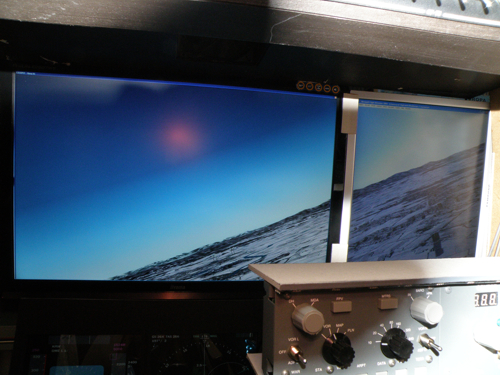
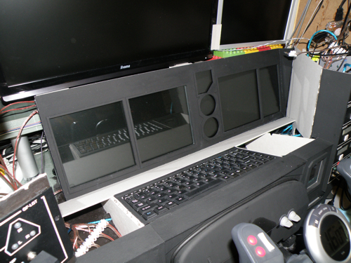
A lot of my cockpit guests
suggested me to enlarge my front view. I was kind of skeptic at the
beginning as I actually didn't need any larger front view - I used
it only for ground operations and visual approaches. Finally I
decided to buy a new 26" Iyama monitor (1900x1200 resolution) and
connect it with a standard 20" (?) monitor put vertically. I didn't
expect anything wonderful but now I can feel a huge difference - it
is more like sitting inside a moving object. Especially during
turns, take-offs, landings and taxiing this feeling is very big.
Large monitor helps a lot during visual approaches too. Anyway, as
you can compare yourself, my current view is more then two times
bigger then it was before. |
 |
|
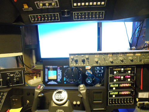
Here is a picture I made after
connecting and configuring all GoFlight modules I have. As you can
see there is no glareshield yet however all avionics work fine. Five
panels are conected to the Client PC, rest to the FS PC. Besides
GFconfig I have used GFKey, GFdisplay and obviously FSUIPC and
WideFS. It took me a long time to understand the rule but now I am
happy because everything works as I expected and I can already make
some in-flight tests. I need to say that using EFIS to control glass
cockpit display is kind of swank! Especially when you imagine, how
long way the electronic signal need to cross and how many times this
signal is being converted to another format by various software. :)
Right now I am using:
GF-MCP Pro
GF-EFIS
GF-LGT
GF-46 x2 (XPDR, ALTM, ADF, DME)
GF-166 x2 (COM 1, COM2, NAV1, NAV2)
GF-P8
GF-T8 x3 (lights, audio, fuel, power, de-ice) |
 |
|
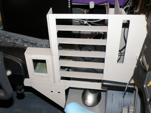
Building
my glareshield was a bit weird as it required a lot of measuring,
calculating, trying and trashing bad parts. Let photos below tell
the story of how it was built. I can just add that I used only 3mm
cardboard for the main construction. Behind my yoke there is a
keyboard and a trackball that controls the Client PC (it helps me
especially while communicating on text during online flying).
  |
|
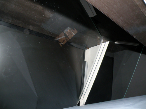
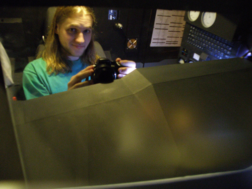
I have decided to order two 5mm glass windows
for my windshield because I expected some better visual effects. I
have made an exact shape from a cardboard which was later used as a
pattern to cut a glass precisely. Of course it wasn't perfectly
aligned but I was able to fix it the way I have planned. The left
photo shows the exact way of fixing my glass windows to the
glareshield and the overhead (both pieces of glass were just
"blocked", no glue was used). The right photo shows... well... guess
whom!
  |
|
After some
"cosmetic" work the second version of my cabin was finally finished
on 17th January 2009. This makes three and a half years from the
very beginning of my cockpit construction. To look at the "finished
product" pictures and movies please go to
Gallery / Video section. To find some more technical specs of my
cabin check the
Information section. You may also visit my
virtual airline's website.
 |
|
This cockpit stayed
intact till 2011. |
|
|